Capacitor Bank Diagram
Capacitor bank diagram wiring power ac step panel reactive circuit building wire switchgear tutorial supplying main connect The basics of capacitor banks protection Capacitor bank diagram step multiple banks fuses
Step-by-step tutorial for building capacitor bank and reactive power
Discharge behavior of capacitor banks 3 phase ct meter wiring diagrams Capacitor bank : types, connections & its applications
Step-by-step tutorial for building capacitor bank and reactive power
Capacitor wiring factor3 phase capacitor bank wiring diagram What is a capacitor bank?Capacitor switchable switched electrical4u.
Wiring pump diagram submersible well phase wire water control franklin capacitor motor volt bank box humbucker kmise diagramfor 230v overloadBank capacitor power connection factor phase wiring meter ct capacitors diagrams diagram factors Capacitor reactive phase panelCapacitor protection banks electrical bank diagram connection power basics relay voltage used reactors equipped inrush industries reactive limit almost etc.

Capacitor bank schematic capacitors discharge voltage high parallel banks pulse assume network let
Capacitor banksPower factor capacitor bank wiring diagram Protection of capacitor banks by fuses during energization andProtection of capacitor banks by fuses during energization and.
Capacitor bank diagram banks schematic applications characteristics figureCapacitor bank diagram power factor connection phase connect three Capacitor bank single diagram fusesCapacitor banks overvoltage inmr.

Capacitor bank electrical engineering
Wiring diagram panel capacitor bank ~ module wiring diagramSwitchable capacitor bank or switched capacitor bank Overvoltage protection of series capacitor banksStep-by-step tutorial for building capacitor bank and reactive power.
Power factor capacitor bank connection diagram,how to connect threeCircuit main bank capacitor panel power connection reactive step cb breaker compensation dots capacitors reactors represents l3 l1 l2 bars .


The basics of capacitor banks protection | EEP

Overvoltage Protection of Series Capacitor Banks

Step-by-step tutorial for building capacitor bank and reactive power

Switchable Capacitor Bank or Switched Capacitor Bank | Electrical4U
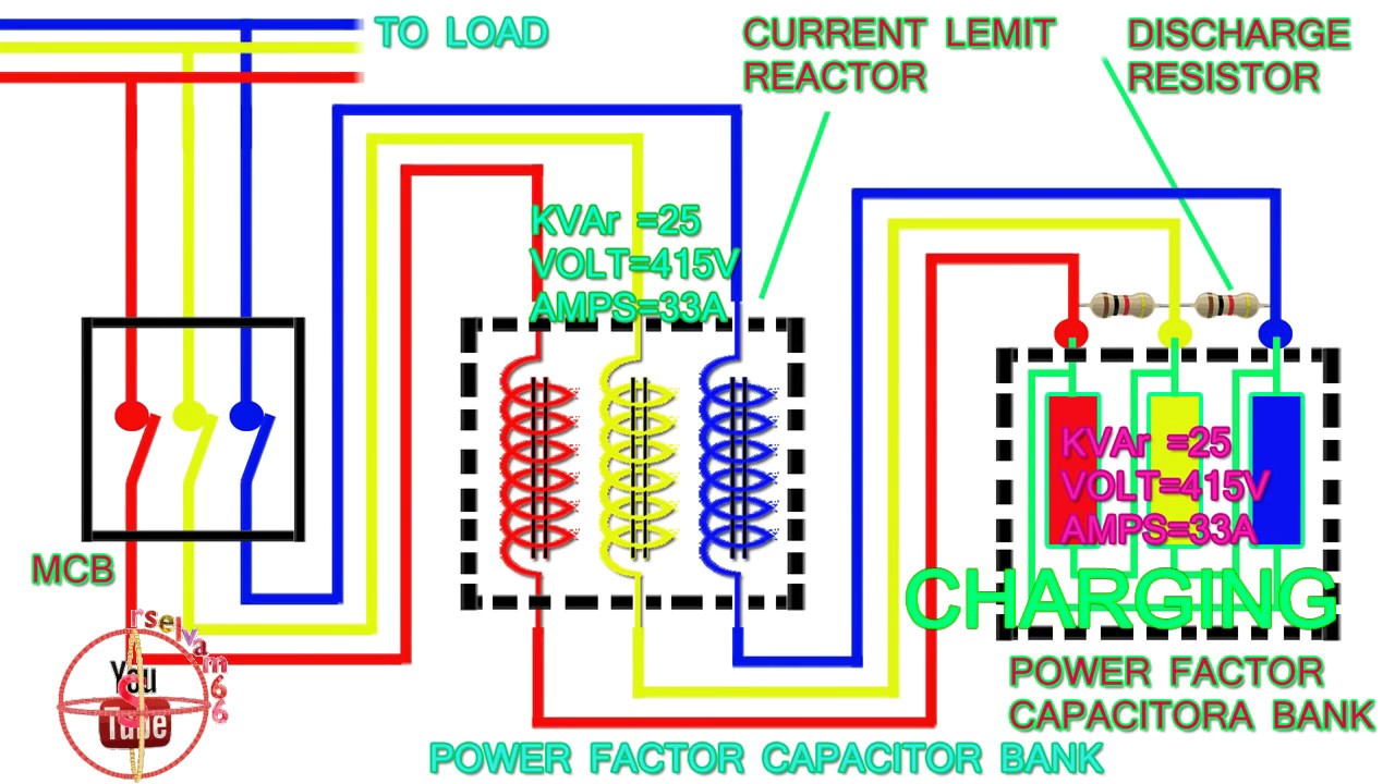
power factor capacitor bank connection diagram,how to connect three

3 Phase Capacitor Bank Wiring Diagram - Free Wiring Diagram

Step-by-step tutorial for building capacitor bank and reactive power

Protection of capacitor banks by fuses during energization and

3 Phase Ct Meter Wiring Diagrams